A Simplified Introduction to the Lean Operation

In today’s business environment, maintaining or increasing market share has always been a challenge to companies. With ever changing customer demands, companies are constantly challenged to offer products and services that appeal to customers. On the other hand, companies are also fighting to reduce operational costs to stay competitive. Regardless of either offering attractive products or services or to maintain operational efficiency, lean operation can be very helpful in either case.

In the manufacturing perspective and as mentioned in Wikipedia, lean (or lean production) is a systematic method towards elimination of waste in the manufacturing system. It can be regarded as one of the approaches in continuous process improvement, together with concepts such as Just-in-time (JIT) and Toyota Production System (TPS). Both JIT and TPS are introduced by Toyota Motors Corporation. JIT is a concept of continuous and forced problem solving that is focused on improving overall production efficiency through streamlined production process and reduced inventory. TPS, on the other hand, is a socio-technical system that focused on standard work practices, respect for people and continuous improvements.

As we know it today, Toyota is the world’s largest automaker in global car sales figure and also ranks at number eight of world’s most valuable brands. The global success of Toyota Motors Corporation has showed how TPS and JIT can maintain great efficiency and responsiveness to the market. One very important feature of TPS and JIT is that while these two operations tend to have internal focus, lean production begins externally with an emphasis on customers. Similar to the “begin with the end in mind” thinking by Steven Covey, lean production starts with understanding what the customer wants and ensuring customer input and feedback are valued. In other words, the workflow is initiated from the customer’s perspective to ensure customer satisfaction.

When implemented as an integrated manufacturing strategy, JIT, TPS and lean production contributes towards overall organizational competitive advantage, better quality management and also increased overall revenue. Today, the term “lean operation” encompasses the aforementioned three strategies with specific focus on waste elimination, removing process variability and an improved throughput.

Wish to know more about which operations are categorized as waste? Do check our blog for more details. Alternatively, you are invited to join our course “Lean Journey to Productivity“, as we take you on a journey to lean.

See SolidWorks What’s New 2016 Part 1

Introduction

Hello all, today title is about “SolidWorks What’s New 2016 Part 1”. SolidWorks What’s New 2016 basically will be separate in 4 pillars. Which is Design, Validate, Collaborate and Build. And this blog will be focus on a part of the ‘Design’ Pillar.

SummaryWN1

This blog highlights the core message on the DESIGN PILLAR. In this video we will show you about the new enhancement on User interface, Sketching and Part modeling.

User Interface Redesign

The SOLIDWORKS 2016 user interface is redesigned to provide better support for high-resolution, high-pixel density displays.

All icons, buttons, toolbar, and text respond well to your Windows display scaling settings.

Visual clutter is removed from the user interface, and a new triad design provides improved visual clarity and ease of use.

New Icon Style

SOLIDWORKS 2016 provides a new icon style that is consistent with the Dassault Systemès portfolio of 3D EXPERIENCE products. It also allows vector-based scaling for superior support of high resolution, high pixel density displays. The new icon syle standardizes the perspective of icons, removes non-essential details, and emphasizes primary elements. Consistent visual styling applies to all icons.

SOLIDWORKS 2016 VS. SOLIDWORKS 2015
WN3 WN2

The visual styling uses blue to emphasize the primary action or feature, dark grey outlining to define the overall icon shape, and shadows for visual grounding.Most icons are similar to previous icons, but with crisper lines that improve readability and recognition. The location of icons on the Command Manager and toolbar has not changed. Finally, the icon color scheme and use of highlights are easier to identify for color blind users.

Redesigned Triad

The triad is redesigned to make it easier to control model orientation in 3D, using selection handles and angle rotation.

On screen manipulators like the triad manipulator, section view triad, and Instant 3D arrows have been redesigned for better visibility and enlarged to be easier to manipulate.

WN4

Moving the Confirmation Corner Options to the Pointer

You can confirm changes you make in sketches and tools more easily by using the keyboard shortcut to move the OK and Cancel buttons to the pointer location in the graphics area.

When you open a Property Manager, the OK and Cancel options are located in the upper left corner of the Property Manager and in the Confirmation Corner, while your pointer may be in the middle of the graphics area where you are manipulating the model.

WN5

To move the Confirmation Corner options to the pointer:

  1. Open a tool.
  2. Use a manipulator to modify a feature.
  3. Click in the graphics area and then press D.

The buttons from the Confirmation Corner move to the pointer position, making it easier to complete the action.

WN6

To move the buttons back to the Confirmation Corner, press D again.

If a Property Manager or sketch is not open, you can also press D to display selection breadcrumbs at the pointer location. See Selection Breadcrumbs on page 29.D is assigned as the keyboard shortcut to move the Confirmation Corner buttons or selection breadcrumbs to the pointer unless you have assignedD as a shortcut for another SOLIDWORKS action.

Selection Breadcrumbs

Selection breadcrumbs are a context-based view of the current selection. They show related elements up and down the hierarchical tree, from the selected entity through the top level assembly or part.

Breadcrumbs let you select something in the graphics area and refine that selection through the context-based representation of the item. For example, in an assembly, when you select a face, you can see all of the mates of the component that face belongs to.

Prior to SOLIDWORKS 2016, to view the mates you either had to right-click the component or find the component in the Feature Manager design tree and open the mates folder.

Breadcrumbs provide access to the entire hierarchical chain of entities from the item you selected up through the top level document. In addition, breadcrumbs provide access to common selections that are adjacent to the entities in the breadcrumb, such as the underlying sketch of a feature, or the mates of a component.

WN7

Selecting Midpoints with Dynamic Highlighting

You can dynamically highlight and select midpoints on sketch entities and model edges to add relations. You can also dynamically highlight and select midpoints of sketch entities while dimensioning in sketches.

Previously, you could only select midpoints of model edges while dimensioning using

Select Midpoint from the shortcut menu. However, on selection of a second midpoint on another entity, the first entity was cleared.

WN8

Show or Hide Sketch Dimensions

You can show or hide 2D and 3D sketch dimensions with the View Sketch Dimensions

functionality.

Previously, only 3D sketch dimensions were hidden when you turned off View Sketch

Dimensions.

Unmerging Sketch Endpoints with Detach Segment on Drag

You can unmerge sketch entity endpoints with Detach Segment on Drag.

Previously, with Detach Segment on Drag, you could drag any sketch entity and detach it from other entities, but you could not detach an entity at just one endpoint.
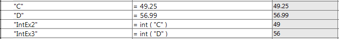
Segment Tool

You can use the Segment tool to create equal length segments in lines,arcs and circles.

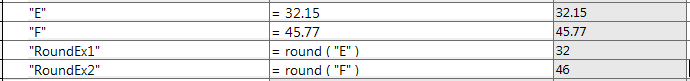
Equidistant Relations

When you use the Segment tool in lines, arcs, or circles, an equidistant relation is applied to the sketch points.

The equidistant relation creates space between the sketch points on the line, arc, or circle.

If you drag or resize the line, arc, or circle, the sketch points automatically adjust to remain equidistant along the segment.

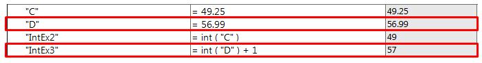
Deleting any of the equidistant relations in a sketch point group deletes the entire relations group. After deleting an equidistant relation, the sketch points remain in their previous locations with a coincident relation to the entity onto which they were placed.

WN9

Thread

WN10

You can create helical threads on cylindrical faces using profile sketches. You can store custom thread profiles as library features.

Using Thread, you can define the start thread location, specify an offset, set end conditions, specify the type, size, diameter, pitch and rotation angle, and choose options such as right-hand or left-hand thread.


Presented to you by:

Joe Lam

Application Engineer, CADVision Systems Sdn Bhd


Design Secrets Revealed

Summary

Let’s take a look at the summary for today. First of all, we will be taking a look at Splines and some of its basic terminology and functions. Then, we will be seeing how we can utilize splines to achieve optimal material flow with some examples even before conducting any simulation/flow simulation on our design. The next portion we will be discussing on sketch blocks in mechanical designs with some examples as well.

Spline Basics

–     3 points make a spline (the fewer the better)

  • With normal spline creations, we just need to input the spline points to create the spline. The lesser the points, the easier it is to manipulate it

–     Spline HandlesB1

  • These Handles allow users to change the degree and length of the spline freely to obtain the desired shape

–     Spline Property Manager

  • In the Property Manager for the spline, users can access to multiple functions discussed in this section

–     Tangency, horizontal, perpendicular constraints

  • Relations can be added to the spline handles to fully define the spline

–     Dimensioning

  • Dimensions can also be added to define the spline

–     Mirroring

  • To obtain a symmetric shape of the spline, the mirror function is crucial to ensure smoothness of the transition

–     Fix

  • By fixing the spline, we can modify other entities around the spline to get our desired design intent

–     Fit Spline

  • Fit spline is used to combine 2 separate splines into one

–     Proportional

  • When proportional is selected in the Spline Property Manager, we can freely change the size of the spline while retaining the overall shapeB1

–     Style Splines

  • New in SOLIDWORKS 2014, the style spline utilizes construction lines to create the spline for easier manipulation of the spline

–     Curvature combs – we see the results as we design!

  • Curvature combs allow us to evaluate the acceleration and deceleration (Smoothness) of the spline curve that we have created


Optimal Material Flow Example

Curvature combs can provide a great insight into our design even before we proceed to perform flow simulation on our design. Consider the following hourglasses. One of them is an ordinary hourglass while the other seems to be magical in terms of the flow rate. Tracing the pictures using the spline tool, we can evaluate the curvature comb for both hourglasses.

B1

B1


The curvature comb of the ordinary hourglass shows that the curve decelerates right at the beginning and the ending, causing the flow to decelerate as it approaches the orifice.
B1


The magical hourglass on the other hand, accelerates drastically near the orifice, allowing the sand to flow quickly at the orifice.


Although the overall shapes of both hourglasses are essentially the same, by using the curvature comb display, we can adjust the shape just slightly to amplify the effectiveness of our design.


Sketch Blocks in Mechanical Design

‘Sketch block’ is a function that groups multiple pieces of sketch geometry and dimensions together, allowing users to move it about as if it is a single entity. Utilizing sketch blocks in layout-based assembly design can create in-context parts straight away from the assembly file itself.

One very handy advantage of using sketch blocks is that we can represent the motion of an assembly in a 2D environment first. Sketch blocks can be saved separately as .sldblk files for easy importation.

When creating a new assembly, click ‘Create Layout’ instead of importing part files.

B1

Then, create sketches and save it as blocks.

B1
B1

Sketch Blocks can be created in either layout-based assemblies or in sketches of parts. Importing multiple sketch blocks into the layout and adding in relations between entities allows users to move/rotate individual blocks as if it is a single part. Using that, we can quickly evaluate the accuracy of our sketches before we create the parts for the assembly.

B1

**For detailed hands-on exercises on these examples of splines and sketch blocks, please refer to the video.


By JJ Chan,

Application Engineer, CADVision Systems Sdn. Bhd.

What you Didn’t Know About Assemblies and Mating

Dear readers! Hi! Welcome to our new website!

Today, we will be discuss on  mirroring, assembly pattern, assembly visualization, Advanced Mates, Mechanical Mates, Exploded Views, and Interference Detection.

Mirroring

Here we start with Mirroring. Mirror components across a plane, you can preserve the mates and motion. When you mirror something, there are 4 choices of orientation of original part. Or create an opposite hand version from within assembly. When you mirror a component, you may create a new configuration in existing part or create a new file.B1

Assembly Patterns

Next thing is assembly patterns, you can pattern components based on Hole Wizard or Pattern features in other components. Pattern in your assembly update automatically if seed feature changes. New in 2014, you can do curve and sketch driven pattern in assemblies, it only available in part until 2014. And also 2014, feature-driven pattern is not call pattern-driven pattern.  Which means any type of pattern can be used as a seed. You can use pattern exist in your part or pattern exist in your assembly.

Next we going to talk about chain pattern and Belt/Chain feature. Chain Pattern in new in 2015, the belt/chain feature is older. Chain pattern creates patterned components group along a sketch or curve path that simulated a chain. One or more components are attached to path and instances are created based on that path. The Pitch method determines how the components chain group or groups are connected to the path. The distance and distance linkage options use a single chain group of components, while connected linkage option uses two chain groups.

B1

Belt/Chain feature creates a virtual belt path which attaches and rotates cylindrical faces. Belt/Chain Assembly Feature adds appropriate mates and relationships to achieve the desired rotational result, and give the option to create a new part from the feature. The Belt/Chain feature creates a sketch that can be made into solid using sweep.B1

Assembly Visualization

Assembly Visualization provides different ways to display and sort an assembly’s components. The list provides an alternative to the feature manger design tree. You can sort the list using basic numerical data such as mass or volume or you can create customized criteria which are dependent on several numerical values. You can also sort by custom properties and add or delete columns.

B1.png

In the graphics area, the software applies colors to the components based on the value of the property you are sorting. The colors help you visualize the relative value of the property for each component.

Advanced Mates and Mechanical Mates

In the Mate Property Manager there are many advanced and mechanical mate types that can accomplish complex relationships. In the Advanced mates, there are Profile Centre Mate, Symmetric Mate, Width Mate, Path Mate, Linear/ Linear Coupler Mate, Distance Limit Mate and Angle Limit. In the Mechanical Mates, there are Cam Mate, Slot Mate, Hinge Mate, Gear, Rack and Pinion Mate, Screw Mate and Universal Joint Mate.

Exploded View

You can make Exploded Views of assemblies by exploding the assembly component by component.  The assembly can then be toggled between normal and exploded view states. Once created, the Exploded View can be edited and also used within a drawing. Exploded view is saved with the active configuration. You can have more than one exploded view per configuration.

B1

Interference Detection

Finding interference between static components in the assembly is the job of interference detection. This option takes a list of components and finds interference between them. The interference are listed by paired components including a graphic representation of the interference.


By Ray Chan,

Application Engineer, CADVision Systems Sdn. Bhd.


Why will SOLIDWORKS® not launch after I have applied Windows Update KB3097877?

A problem has been identified with Windows Update KB3097877. After installing this update SOLIDWORKS® can fail to launch. A newer version of this specific Windows Update has now been released to resolve this issue.

If your computer shows symptoms of crashing during launch after applying this Windows update please follow these steps to resolve the problem:

1. Uninstall the original Windows Update KB3097877.

  • Open Installed Updates by clicking the Start button Picture of the Start button, clicking Control Panel, clicking Programs, and then, underPrograms and Features, clicking View installed updates.
  • Click the update that you want to remove, and then click Uninstall. Administrator permission required If you’re prompted for an administrator password or confirmation, type the password or provide confirmation.

To learn more about how to uninstall windows, please visit:

http://windows.microsoft.com/en-us/windows/remove-update#1TC=windows-10

2. Download the newer version of the update from the Microsoft® download site:

https://www.microsoft.com/en-us/download/confirmation.aspx?id=49787.

3. Install the new version of the Update.

For more details, you can access to solution ID: S-070223 via SOLIDWORKS customer portal.

And you’re done!

Kindly contact to your reseller if you need further assistance. Or you may contact us at support@cad-vision.com or call +603-2630 6118 for support.

Prepared by,
Nick Lai
SNS Editorial, CADVision Systems Sdn. Bhd,

SOLIDWORKS Vs. Windows 10

It’s been a while that Microsoft® announced that Windows 10® is now available for business. And here’s the questions strike in our mind… Should I upgrade the operating systems to Window 10?

Is my SOLIDWORKS’ version compatible with Windows 10?
You might find yourself the answer from the table below which is taken from the SOLIDWORKS official website:

Sources: http://www.solidworks.com/sw/support/SystemRequirements.html

To summarize the table, we could see that
(1) SOLIDWORKS 2014 and SOLIDWORKS 2015 SP 4.0 or older version will NOT support Windows 10
Meanwhile,
(2) SOLIDWORKS 2015 SP 5.0 and newer version is compatible with Windows 10

Therefore, we will recommend the user not to upgrade the operating systems until SOLIDWORKS has released versions (2016 SP 5.0 or newer versions) that officially support Windows 10. However, if you’ve upgraded the o.s to Windows 10 and you’d like to update your SOLIDWORKS license to the Windows 10 compatible version, feel free to contact us at info@cad-vision.com

Or
If you have any other inquiries, please do not feel hesitate to contact us at +603-2630 6118
Prepared by Nick Lai
CVS SNS Editorial, CADVision Systems Sdn. Bhd.

Using SOLIDWORKS Equations

SOLIDWORKS Equation features is a powerful and convenient feature to allow users to define dimensions using global variables and mathematical functions, and furthermore create mathematical relationships between two or more dimensions in your part and assembly designs.

However, most of the time is that users are only using the most basic capabilities of SOLIDWORKS Equation without realizing the advanced operators that are available. As such, this article introduces some of the operators or Visual Basic key words.

A commonly used operator would be the “IF” Operation, where users are able to include a “If, Then, Else” mathematical condition to their designs.

The example below shows a simple example of the “IF” Operation usage.

This cube has been constructed with a height of 100mm, width of 150mm and a length of 200mm by including the global variable as below:

A = 150

B = 200

For this example, lets control the design so that when the height of the cube exceeds a certain number (>120mm), the length of the cube will be increased to 250mm instead.

To do so, we have to go to the Equations, Global Variables, and Dimensions window. Under the B global variable, instead of inputting 200mm, we are going to input the “IF” Operation which will have the format:

DimensionValue = IF(ConditionValue>X, ThenValue, ElseValue)

Based on our condition for the cube, our input for the formula will be as shown. When constructing the equation, the ConditionValue will be an input by selecting the dimension from the graphics area of SOLIDWORKS.

This equation dictates that if the height of the cube exceeds 120mm, the length of the cube will increase to 250mm, or else if the height is below 120mm, the length will remain as 200mm.

Let’s try to change the height from 100mm to 130mm and see if our equation works.

We see how it will automatically update the length to 250mm. Now let’s try a height of 110mm and see what happens.

Another useful tool that users can benefit from is the integer, int() function and the round, round() function. Let’s take a look at the integer, int() function first. Here we are going to add in this function into our global variable. As seen in the figure below, you will notice that the integer function rounds DOWN any value with decimal places to the nearest whole number.

So what about the round function? What the round function does in SOLIDWORKS is that it will round up any values with decimal places to the nearest whole value, UPWARDS or DOWNWARDS. Anything below a decimal place of 0.5 will be rounded down and anything equal 0.5 or above will be rounded up. For example:

Let’s add a few round, round() functions into our example. The E and F values will be rounded up or down depending on the decimal places.

But what happens if we want our decimal values to always round UPWARDS only? Although SOLIDWORKS equations does not have a direct function that allow users to do that, there is a workaround to go about solving this tricky situation. All we need to do is to add a “+1” after our integer, int() function. Let’s do that by revisiting the existing example that we have here:

As such we are able to have the “IntEx3” Global Variable to always round up to the closest value, in this case for 56.99, rounding it downwards to 56 using the integer function and then adding 1 to make it 57.  But of course the few functions introduced here are not the only ones available in SOLIDWORKS, so do continue exploring the other capabilities of SOLIDWORKS Equation!


Prepared by JJ Chan,

Application Engineer, CADVision Systems Sdn. Bhd.

p/s: Suggest us a topic that you would like to discover by sending us an email to eventpg@cad-vision.com